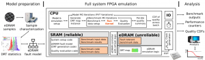
This platform is based on an FPGA emulation framework with an eDRAM hardware model which emulates faulty eDRAM behavior in a full embedded computing system [1].
The main features are:
- This framework enables statistical analysis of error resilience in embedded applications that employ eDRAMs with sub-critical refresh rates beyond the data retention time (DRT) limit.
- A physical model of errors in eDRAMs is developed with sufficient abstraction to enable FPGA implementation. It is based on the notion of DRT maps which can be obtained from silicon measurements or based on statistics.
- We implement a corresponding eDRAM emulator that injects errors on the bit-level due to DRT violations with cycle-accuracy.
- The register-transfer level (RTL) code and the peripheral component for Xilinx Vivado is provided.
- The eDRAM emulation is integrated into an embedded system built with Xilinx Vivado and a Xilinx MicroBlaze soft-core CPU connected to our cycle-accurate eDRAM emulator featuring a configurable statistical error-model within the same FPGA.
- The model can be integrated into the FPGA emulation of any embedded system for fast statistical evaluation of the quality of software applications under the effect of memory errors.
How to use:
- Download the emulator by clicking on this link and unzip the content of the file.
- Open Vivado 2008.2 and run the following commands in the Tcl Console:
cd path/to/this/directory
cd hw
source create_project.tcl
- Use the GUI to generate the bitstream and program it to the VC707 FPGA board.
- Open a terminal and run the following commands:
cd path/to/this/directory
cd sw/benchmarks/convolution
make run
- A test program will be compiled and executed on the emulation platform. The output will be printed to the UART output of the board (baud: 115200).